Category Archive: Heat Exchanger Design
Tag Archive: Heat Exchanger Design
-
-
Welcome to Enerquip Heat Exchangers
Leave a CommentThe helpful heat exchanger experts at Enerquip have been designing and fabricating shell and tube heat exchangers for our customers’ production plants since 1985.The Enerquip team is passionate about not only building heat exchangers, but building the best heat exchanger solutions for our customers. Enerquip’s culture is built around integrity. Our team is never done learning, never done growing, and never satisfied with “good enough”.
Welcome to Enerquip!
-
Heat Exchanger Helps Aloe Processor Improve Quality
Leave a CommentIn 2012, a producer of pure aloe for medicinal and nutritional products approached Enerquip with a unique cooling problem. In the tropical region where aloe is harvested, the ambient temperatures hover near 95° F (35°C) most of the time. This tropical climate was accelerating bacterial growth in the product, which was lowering its value and shelf life. Enerquip worked with the producer to develop a solution using a shell and tube heat exchanger.
Ideal conditions for the product were discovered after performing some testing. The aloe producer found that if they could cool the product below 40°F (4.4°C) before packaging it, there was a significant improvement in quality.
However, the customer’s lack of utilities at the packaging site led to complications in the cooling process. They had electricity, but the cooling water system already in place did not supply water that was cold enough to provide the low temperatures necessary to impede bacterial growth. Also, the staff using the equipment was not technically inclined, so any solution needed to be easy to control and understand. Because the aloe processor only packed the product several times per season, the equipment needed to be easy to clean, move and store during the off-season.
After reviewing the process and existing equipment, the thermal team at Enerquip realized that a heat exchanger was required for the application. Heat exchangers are built for efficient heat transfer from one medium to another. There are multiple types of heat exchangers that offer the ability to either separate the media or, for them, to be in direct contact.
Shell and tube heat exchangers consist of a series of tubes inside a larger pipe. The tubes contain the product, which is the fluid being heated or cooled. The second fluid – a heating or cooling medium – fills the larger pipe around the outside of the tubes, with the heat transferring between the product and the medium through the tube walls.
During the heat exchanger sizing and selection process, several factors are taken into account:
- The product specifics
- Temperature (in/out)
- Flow Rate (product quantity in/out)
- Cooling medium
- Temperature and size limitations
The ability to easily clean the equipment played a major role in this application. Aloe is a very viscous product, and due to the frequency of use, it became evident that a shell-and-tube heat exchanger would best fit this application. The exchanger was designed in a straight-tube, multi-pass configuration, which allowed the product to travel back and forth through the exchanger several times before heading to the packaging line. The straight tube exchanger option with removable bonnets allowed for easier mechanical cleaning than other designs.
Due to ground water availability and temperature at the plant location, a chiller was added to complete the process for this application. The air-cooled chiller was installed and utilized to provide enough cold glycol and water to cool the aloe product in a single pass through the exchanger. Once filled with glycol and water, the chiller only needed plant electricity to run. The chiller supplier installed simple pushbutton procedures that were easy for the plant staff to follow. Independent shut-off valves and removable hoses between the chiller and exchanger also allowed for easy tear down and cleaning following production.
The end results of this process provided the aloe producer with an efficient system and cleaner, colder and more valuable aloe products.
Click here to read more about the Aloe Vera processing.
-
Shell-Side Fluid Challenges: Increasing the Pressure Drop
Leave a CommentBefore constructing a shell and tube heat exchanger, it’s crucial to carefully design it to ensure it performs optimally within the specific system it’s meant to serve. The design process involves multiple considerations, with one of the most important being pressure drop.
What is Pressure Drop?
Pressure drop refers to the loss of pressure that occurs as a fluid moves through the heat exchanger. It’s a critical factor in determining the heat exchanger’s efficiency. However, there is no one-size-fits-all target for pressure drop. The ideal pressure drop depends on the heat exchanger’s application, its design, and the type of fluid being processed.
Every heat exchanger has a maximum allowable pressure drop — the upper limit beyond which performance or equipment safety could be compromised. The goal of the designer is to get as close as possible to this maximum without exceeding it. Achieving this balance often requires careful adjustments — in some cases reducing pressure drop, and in others, strategically increasing it.
Pressure Drop and Fluid Velocity: A Balancing Act
Generally, higher fluid velocities lead to higher pressure drops. So, when the pressure drop is too high, engineers typically reduce the flow rate to bring it within acceptable limits. On the other hand, if the pressure drop is well below the maximum allowable value, this could signal that the heat exchanger isn’t operating at its full potential. In such cases, increasing fluid velocity could help enhance heat transfer efficiency.
In essence, when there’s room to approach the maximum pressure drop, designers may look for ways to increase the fluid velocity, improving the heat exchanger’s overall performance.
Strategies for Increasing Shell-Side Pressure Drop
Pressure drop is closely tied to the flow rate of the fluids within the heat exchanger, especially on the shell side. If the goal is to increase pressure drop for better performance, several design modifications can help achieve this:
- Opt for a Smaller Shell Diameter
A smaller shell diameter can increase shell-side fluid velocity, which in turn can increase pressure drop. Custom-built heat exchangers can be designed to maximize this effect. However, designers must be cautious of the potential impact on tube-side pressure drop. A shell that’s too small may cause the fluid in the tubes to flow too quickly, potentially surpassing the maximum allowable pressure drop. - Adjust Baffle Spacing and Cut
Baffles play a vital role in controlling the direction and speed of the shell-side flow. By reducing the spacing between baffles, you can increase fluid velocity, leading to a higher pressure drop and a greater heat transfer rate. However, it’s important to ensure that baffles are spaced according to specific guidelines: for example, in exchangers with a shell diameter of 10 inches, baffles should be spaced at least 2 inches apart. For larger shells, baffle spacing should be a minimum of one-fifth of the shell’s internal diameter. - Optimize Tube Configuration
The arrangement of the tubes within the heat exchanger impacts the flow characteristics of the shell-side fluid. For instance, triangular tube patterns allow for higher fluid velocity compared to square patterns, which can help achieve a higher pressure drop and stronger heat transfer. However, this configuration can make cleaning more challenging, which is why it’s typically chosen for applications where chemical cleaning is used.
Pressure Drop: A Double-Edged Sword
While pressure drop challenges are most commonly associated with excessively high flow rates, there are instances where engineers intentionally work to increase both velocity and pressure drop to achieve a more efficient heat exchanger. This delicate balancing act is essential for designing heat exchangers that perform at their best.
At Enerquip, our engineering team specializes in solving complex design challenges. We work closely with our clients to craft custom shell and tube heat exchangers that meet their unique operational needs. If you’re facing pressure drop or heat exchanger performance issues, don’t hesitate to reach out. Let’s work together to create the perfect solution for your system.
More from the Enerquip Blog
- Exploring Electrolysis as a Leading Hydrogen Production Process
- Selecting Tube Sizing in a Shell and Tube Heat Exchanger
- Shell and Tube Heat Exchangers Used to Cool Wort in Craft Brewing
- Choosing Between a Straight Tube and U-Tube Heat Exchanger Design
- 5 Ways Shell & Tube Heat Exchangers Help Recover Waste Heat
- Opt for a Smaller Shell Diameter
-
Helpful Details to Consider When Selecting a Heat Transfer Fluid
Leave a CommentThe heat transfer fluid (HTF) flowing through your shell and tube heat exchanger plays a large role in determining the effectiveness of your operation. Many options are available for HTFs, including water, steam, mineral oils, silicone-based fluids and glycol-based fluids.
HTFs flow through either the tubeside or the shellside of the shell and tube heat exchanger, while the product being treated flows through the opposite side. The fluid facilitates either the heating or cooling of the product.
Choosing the right HTF for your operation involves many considerations. Here are some key details to know about HTFs:
Cost and Accessibility
HTF selection shouldn’t be entirely based on cost, but this is a key factor to take into account. The fluid you choose should also be easily accessible so that you can replace it when the time comes.
Glycol-based HTFs are popular among many industries and applications for both of these reasons, according to a webinar from Process Heating summarized in the Journal of Applied Mechanical Engineering. Silicone HTFs are also common among many industries, Processing Magazine noted.
Glycol-based HTFs can also be combined with water to reduce the freezing point and increase the boiling point. No other HTF can be diluted with water safely.
Allocation
It’s important to choose wisely when determining whether to allocate your HTF to the shellside or tubeside of your heat exchanger. The most beneficial side is one that provides you with the least risk of cross-contamination, easiest cleaning and the safest operation. However, these factors are dependent on the design of the shell and tube heat exchanger, the application and the type of HTF you’re using.
The tubeside of your heat exchanger is most beneficial if your fluid is:
- High pressure.
- Prone to fouling.
- Corrosive.
- Likely to solidify.
A tube bundle is much easier and less expensive to remove and install than a shell, which often requires the replacement of the whole unit. That means if a fluid corrodes tubes beyond safe use, or solidifies to the point of complete obstruction, the bundle can be removed relatively easily and swapped for a new model.
High pressure fluids are better off on the tubeside because the pressure can be controlled by using smaller diameters. This is much more practically done with tubes than shells, which need to have larger diameters to accommodate the tubes within.
Finally, tubes are generally easier to clean on most shell and tube heat exchanger designs. Because of this, a fouled tube is simpler to remedy than a fouled shell.
If your fluid has a low pressure drop or will condense, it may be better off on the shellside. Pressure drop requirements are easily accommodated with careful shell design and baffle placement. Fluids that are highly viscous are also often allocated to the shellside, as these options tend to have low heat transfer.
Monitoring
Regardless of which HTF you choose, it’s important to regularly inspect its effectiveness regularly. In time, HTFs will degrade, reducing their heat transfer capabilities and increasing risk of damage or corrosion to the heat exchanger.
As the HTF degrades, its viscosity and operating temperature will be impacted. Fluids that are past their prime will be less viscous, meaning it’s more resistant to even flow. Lower viscosities require more energy to pump the HTF through the exchanger.
Continually using degraded fluids will increase the likelihood of the fluid and equipment to overheat. As the fluid decomposes, it may begin to reach higher temperatures, which can damage the product as well as the equipment. Additionally, as the fluid reaches higher temperatures, it will degrade faster.
Carefully Plan Your Shell and Tube Heat Exchanger
Choosing your HTF strategically is important to ensuring a safe, effective and sanitary operation. However, it’s just one component in a much larger puzzle. When designing your shell and tube heat exchanger, it’s important to consider the application, working conditions, material selection and the products that will come in contact with the equipment.
The knowledgeable engineers at Enerquip have broad experience designing and fabricating shell and tube heat exchangers for operations in many industries, including food and beverage, oil and gas, pharmaceutical and more. When you’re determining how to best design your heat exchanger for your operation, reach out to the helpful heat exchange engineers at Enerquip. We can assess your process and all related components, including HTF selection, to design a shell and tube heat exchanger that will benefit your business.
Need a unit or spare part quickly? We stock a variety of sanitary U-tube exchangers for fast turnaround.
-
Metal Expansion Bellows vs. Packed Expansion Joints
Leave a CommentTo few engineers’ surprise, shell and tube heat exchangers can get very hot at times. When that happens, the rising temperatures can cause the unit to swell, a process called thermal expansion.
If a shell and tube heat exchanger is not equipped to handle thermal expansion, the added pressure and changing dimensions of the tubes or shell can cause serious damage to the unit. Tubes and shells often do not expand at the same rate due to differences in material composition, varied temperatures and other factors.
If, for example, tubes begin to expand faster than the shell, they can cause damage to the interior of the shell. Conversely, if the shell begins to expand, the tubesheet can be negatively impacted.
Luckily, there are numerous ways to deal with thermal stress before it comes a costly issue. One such method is to install expansion joints. However, these add-ons aren’t a one-size-fits-all solution. There are numerous categories of expansion joints, and each one has its own set of considerations to take into account.
Two of the most common types of expansion joints are metal expansion bellows (sometimes called packless expansion joints) and packed slip expansion joints.
Metal expansion bellows: pressure placement
Metal bellows can either be internally or externally pressurized. The type chosen depends on the application and environment of the equipment.
Internally pressurized expansion joints Internally pressurized expansion bellows are excellent for operations that require frequent inspections of equipment. It’s easier to review the condition of internally pressurized expansion joints than their externally pressurized counterparts, Chemical Processing explained. Additionally, they’re less expensive, making them a cost-effective option.
However, there are a few downsides to investing in an internally pressurized expansion joint. These designs can’t accommodate large amounts of thermal stress or expansion, particularly when it comes to axial movement. Internally pressurized versions tend to “squirm” under too much pressure, or when accommodating high pressure on long bellows.
For these reasons, internally pressurized bellows are best used as a cost-effective method to combat small amounts of thermal stress.
Externally pressurized expansion joints
Externally pressurized bellows have a few advantages over internally pressurized models, even though they are often more expensive. These are built with a strong outer pipe and an expanding inner lining. This construction also makes them safer because the pressure is contained within the outer pipe, preventing any material inside the unit from escaping, should the bellows fail. Additionally, the outer pipe absorbs shock if there’s an anchor failure.
These models can handle much greater amounts of thermal stress and expansion, making them ideal in most operations that encounter these types of issues. In situations where internally pressurized versions might squirm or outright fail, externally pressurized bellows can hold strong.
They can be customized to minimize leakage in the event of an equipment malfunction or damage. Additionally, they can be designed to be self-draining, adding yet another layer of protection against cross-contamination.
“The size, shape and method of fabrication all determine key characteristics of the bellows.”
Expansion bellows: wall thickness and construction
The size, shape and method of fabrication all determine key characteristics of the bellows. To determine the best wall thickness and other qualities for the bellows, fabricators need to know details of the operation, such as how much pressure the expansion joints will need to withstand.
Thick-walled expansion bellows
Thick-walled expansion bellows are typically between 4 and 13 millimeters thick, often matching the material and thickness of the shell itself. These designs are primarily used in fixed tube sheet shell and tube heat exchangers. Though they are highly durable, they’re also very stiff and have very limited flexibility. They usually only have two or three convolutions, but the convolutions are exceptionally tall – between 75 and 150 millimeters – compared to thinner walls. Thick-walled bellows are usually made by pressing and welding.
Thin-walled expansion bellows
Thin-walled expansion bellows are usually between 0.5 and 2 millimeters thick. While this means they are much more flexible than thick-walled versions, it also means they’re more prone to damage. Because the thin-walled bellows are more pliable, manufacturers can include more convolutions than with thick-walled bellows, and the convolutions are typically between 25 and 75 millimeters tall. Thin-walled bellows are usually made through cold rolling or hydraulic forming.
For operations that involve high pressures but require the thin-walled bellows, fabricators might opt for a multi-ply construction, where multiple layers of the thin metal lie atop each other to bolster and strengthen the bellows. Another method of reinforcing thin-walled bellows is through installing restraining rings, which are usually located outside the bellows at the root, or the lowest point of the curve, according to a research paper from the International Association for Structural Mechanics in Reactor Technology.
Medium-walled expansion bellows
In certain situations, neither thin- nor thick-walled bellows are ideal for accommodating thermal stress, and a compromise needs to be made. Medium-walled models are typically between 2 and 4.5 millimeters thick, offering greater durability than thin-walled versions. They are also more flexible than thick-walled bellows, and have convolution heights of between 50 and 65 millimeters. Medium-walled bellows are usually made by hot rolling.
Packed slip expansion joints
Another common type of expansion joint is the packed slip expansion joint, sometimes simply referred to as slip expansion joints or packed expansion joints. This design includes a sleeve which extends outward from the body of the exchanger as thermal expansion increases, as well as packing installed between the sleeve and the body that helps prevent leaking.
“Packed slip expansion joints are ideal when the thermal expansion causes axial movement.”
These are more often used with packed floating heads, and are ideal when the thermal expansion causes axial movement. Because these expansion joints are composed of two cylinders – the sleeve and the shell – they can’t expand in any other direction other than left and right (or up and down, depending on the orientation of the unit). Any lateral expansion or rotation due to thermal stress would most likely break these joints, according to Piping Guide, a blog written by engineer Ankit Chugh.
One of the downsides of packed slip expansion joints is their susceptibility to leakage. Though the packing is supposed to prevent this, it can’t provide a guarantee that no leaks will occur. Additionally, as the material wears away over time through many uses, a leak will become more likely. Because of this, operations where no cross-contamination can be tolerated would be better off using a different type of expansion joint.
However, where small leaks won’t cause too much concern, a packed slip expansion joint can be an economical way to deal with thermal stress.
What is the best expansion joint for your equipment?
Clearly, there are many factors that impact your decision when weighing your options for expansion joints. To determine the best choice for your shell and tube heat exchanger, it may be most helpful to speak to an engineer well-versed in the design and fabrication of these units.
The knowledgeable engineers at Enerquip enjoy taking on new problems and coming up with the perfect solution for their customers. They’ll work with you to determine your unique needs and find the right expansion joint for your operation. To connect with an Enerquip engineer, request a quote with our simple online form.
-
Condensing Economizers Can Help Operations Reclaim Latent Heat
Leave a CommentBoilers involve a lot of energy and heat, much of which can be wasted if a system isn’t designed to prevent this. One way to capture and reuse lost heat is through installing a condensing economizer. This item captures water vapor and heat, turning it into usable energy.
Condensing economizers have a place in virtually every industry. Food processing plants, greenhouses, pulp and paper mills, hospitals and even district heating systems all utilize boilers and have the potential to use economizers. Investing in one can reduce energy requirements and cut operational costs.
However, condensing economizers typically don’t come in a one-size-fits-all format. They often require highly specialized design and are fabricated to meet the specific needs of one facility’s operations.
How Condensing Economizers Work
In most natural gas-fired boilers, it’s tough to cool flue gas much lower than 250 degrees Fahrenheit, according to the U.S. Department of Energy. Beyond this point, the gas can begin to condense, and the resulting vapor can become corrosive, posing a threat to the integrity of the stack or stack liner. However, for the flue gas to be captured and used as boiler feedwater, it needs to be cooled below its natural dew point of 135 degrees Fahrenheit.
Condensing economizers collect flue gas and cool it to the appropriate temperature, allowing the economizer to reclaim sensible heat (in the form of flue gas) and latent heat (in the form of flue gas water vapor). The amount of latent heat that’s recoverable depends on the type of fuel used, the style of condensing economizer used and other factors.
Types of Condensing Economizers
There are two types of condensing economizers that plant managers or other decision makers can choose from: direct and indirect.
A direct contact condensing economizer includes a vapor-conditioning chamber that’s connected to a countercurrent spray chamber, the Department of Energy explained. Inside the spray chamber, droplets of cool fluid come into contact with the hot gas to facilitate the heat exchange. The droplets cool the stack gas. This option provides a high heat transfer rate and allows for relatively easy water recovery, though this method can only heat water to about 140 degrees Fahrenheit. This style requires a mist eliminator, which prevents droplet carryover.
An indirect contact condensing economizer utilizes a shell and tube heat exchanger to capture the flue gas. This style offers greater heating and cooling capacity; water can be heated to as much as 200 degrees Fahrenheit and cooled to as low as 75 degrees Fahrenheit.
One example of an indirect contact condensing economizer successfully helping reduce costs and energy requirements was detailed by the Department of Energy. A food processing facility wanted to reduce its deaerator steam requirements, which were 5,000 lbs per hour. The company installed the economizer, which served to lower flue gas temperatures from 300 degrees Fahrenheit to 120 degrees Fahrenheit. The process allowed them to capture 2 million British Thermal Units per hour, and effectively cut its deaerator steam requirements down to 1,500 pounds per hour.
Considerations for Condensing Economizers
For both direct and indirect contact condensing economizers, the water exiting the system is usually very acidic and should be neutralized before being used as process water or directed to a sewage system. External heat exchangers, membranes or pH control systems are all viable options for this.
Choosing the right materials of construction is an important aspect of designing a heat recovery system with an economizer. Because the water vapor can be highly acidic or otherwise corrosive, the fabrication materials should be resistant to wear. Stainless steel and similar alloys typically hold up well when exposed to water vapor that comes as a result of hydrocarbon fuel combustion, which is the case with natural gas-fueled boilers.
The space in which the economizer will be used should also be carefully analyzed. For operations where most of the deaerator steam comes from blowdown heat recovery, there is limited potential for cost savings with an economizer. Additionally, operations where there isn’t much need for cold or low-temperature water, a direct contact condensing economizer won’t be especially helpful.
Working with heat exchanger experts such as those at Enerquip can help you determine your needs and the potential for heat recovery at your facility. Enerquip’s engineers will help you design a shell and tube heat exchanger that suits your specific operation. Request a quote, today.
-
Horizontal vs. Vertical Baffles: Which to choose for your shell and tube heat exchanger
Leave a CommentBaffles are one of the most important structural features of a shell and tube heat exchanger. These metal plates are installed throughout the length of the shell and serve three functions, each equally important to the operation of the unit.
First, baffles physically support the tube bundle. They also help maintain tube spacing, preventing the individual tubes from shaking, breaking or bending when the rate of flow or heat transfer causes vibration. Finally, they determine the direction of the shellside flow.
This final purpose – defining the flow path – is critical to the effectiveness of heat transfer and is highly variable. Fabricators have many options in regards to the direction, size and spacing of baffles. One decision fabricators need to make is whether to position baffles vertically or horizontally.
Horizontal Baffles
Horizontal baffles are ideal for operations where a single-phase fluid is on the shellside because this prevents deposits from building up on the bottom of the exchanger, Rajiv Mukherjee explained in an article for Chemical Engineering Progress. It also prevents stratification, allowing warmer fluid in the upper region of the exchanger to mix with colder fluid below.
“Horizontal baffles can often provide a higher heat transfer rate.”
Horizontal baffles are often the default design, with many shell and tube heat exchanger calculations assuming that baffles will be installed horizontally, Koorosh Mohammadi explained in a thesis written for the University of Stuttgart. Mohammadi found through his studies that orientation has a significant effect on pressure drop and heat transfer rate.
When the shell and tube heat exchanger doesn’t have any leakage flows, horizontal baffles generally provide the greatest benefit, regardless of shellside fluid. Heat exchangers with horizontal baffles can often provide a higher heat transfer rate because with this type of design, the average distance between the inlet and outlet valves and the first and last baffles is longer than in exchangers with vertical baffles. Because of this, the amount of shellside fluid traveling alongside the baffle itself is greater, which contributes to increased flow between the tubes and baffles, Mohammadi explained in a different paper on which he collaborated with Wolfgang Heidemann and Hans Müller-Steinhagen for the Institute of Thermodynamics and Thermal Engineering at the University of Stuttgart.
When the shellside fluid moves at a lower velocity, horizontal baffles can help keep the process flowing regularly. Vertical baffles increase the time fluid remains in the shell, which can have a negative effect on heat transfer.
Vertical Baffles
Vertical baffles can simplify the fabrication of two-pass exchangers, such as the F-type shell. This style is also ideal for operations where there is condensation on the shell side. The vertical orientation allows the condensate to travel downward toward the outlet rather than being trapped by the baffle itself.
Mohammadi found that shell and tube heat exchangers with leakage flows perform best with vertical baffles. The benefit is most noticeable when the shellside fluid is gaseous due to the higher dissipation rate of gases compared to liquids.
“Vertical baffles may be best when a lower pressure drop is desired.”
The pressure drop seen in heat exchangers with leakage flows and horizontal baffles is much higher than that in exchangers with leakage flows and vertical baffles. As such, for shell and tube heat exchanger designs aimed at minimizing pressure drop, vertical baffles may be best. Mohammadi found that this orientation combined with baffle cuts that are 30 percent of the shell diameter have the lowest pressure drops. Meanwhile, the highest pressure drop was seen in horizontal baffles cut to 20 percent of the shell’s diameter.
The way baffles are installed into a shell and tube heat exchanger will have a direct impact on the heat transfer rate and pressure drop of the unit. However, the most beneficial baffle orientation depends on the use of the exchanger, the characteristics of the processes it’s used for and the desired effects. Not all processes require the same design, and in many cases, a custom shell and tube heat exchanger provides the best match for a particular operation.
Enerquip’s shell and tube heat exchanger experts have designed and fabricated custom units for a wide range of industries. They work directly with their clients to ensure the final product is one that’s uniquely supportive of their needs. To learn more about how a custom shell and tube heat exchanger can benefit your operation, fill out our online quote request form.
-
Three Types of Mechanical Failures in Shell & Tube Heat Exchangers and How to Prevent Them
Leave a CommentShell and tube heat exchangers are well favored by plant engineers for their long life spans and minimal maintenance needs in addition to their ability to efficiently transfer heat. While stainless steel heat exchangers are reliable and durable for the most part, there are times when stress and extended use take their tolls on the equipment’s components.
Mechanical failure can appear in several different forms, each with its own symptoms and consequences. When you know what to look for, you can work to prevent mechanical failure in your exchangers or identify an issue quickly so you can solve it promptly. Here are three types of mechanical failure that shell and tube heat exchangers can sustain in time:
1. Fatigue
Repeated thermal cycling can lead to fatigue in shell and tube heat exchangers. Fatigue can cause cracking in the tubes beginning with small, hard-to-see striations that can quickly grow larger. Eventually, fatigue cracks can span the diameter of the tube and completely sever it.
There are several factors that can increase the risk of fatigue or cause it to escalate more quickly. A report on failure analysis of shell and tube heat exchangers from the College of Engineering Pune in Maharashtra, India, explained that the stress ratio can play a big role in contributing to thermal fatigue. As may be expected, when stress increases, so does the risk of failure due to fatigue.
“Small weld defects can lead to fatigue and severe damage.”
Another factor that can lead to fatigue faster is poor welding practices, as well as other fabrication shortcomings. In one failure analysis published in Case Studies in Engineering Failure Analysis, engineers determined that a faulty weld joint where the tube met the tubesheet was the catalyst that resulted in failure. After careful review, the team identified a small welding defect, just 0.4 millimeters long, which was the first crack that would eventually lead to dozens of small fractures throughout the tube. With use, the cracks grew and propagated.
In addition to the welding defect, issues with thermal expansion also caused serious stress on the tube-tubesheet joint. The report noted that it’s best to have expansion positions 15 or more millimeters away from the tube end to lessen the stress expansion would have on the tubesheet. In the failed exchanger, the expansion position was very close to the tube end, which likely caused even greater stress on the already faulty weld joint.
Avoiding fatigue must begin with fabrication. Even a tiny 0.4-millimeter mistake can lead to severe damage to the exchanger. Additionally, understanding how to adjust your process to reduce stress within the equipment can help.
2. Metal erosion
Metal erosion in stainless steel shell and tube heat exchangers negatively impacts the quality of the equipment in two ways. First, as metal erodes away from the tubes, they become weaker and more susceptible to damage. Second, as the protective outer layer of the tubes wears down, the tubes face a higher risk of corrosion. Any corrosion already forming will only get worse as metal erosion takes place, according to Plant Engineering.
Metal erosion can be caused by excessive speed of flow within the exchanger and by abrasive solids suspended in slurry streams. When a high-velocity stream is divided into thin, sharp jets of fluid upon entering the heat exchanger, it can also lead to metal erosion. In cases like this, the erosion pattern is horseshoe shaped and very localized. Additionally, high temperatures, such as those that allow for flash steam to occur, can also increase the risk of metal erosion. Plant engineers are most likely to see metal erosion occur on the bends of U-tubes or at the tube entrances.
To prevent metal erosion, it’s important to understand the maximum velocity fluid within the exchanger can reach without causing harm to the components. This largely depends on the materials of construction, the fluid type and temperature, among other factors. Stainless steel fabrication, for example, can handle much higher velocities than a copper shell and tube heat exchanger. Other alloys that contain steel, stainless steel and copper-nickel combinations are also sturdy and can handle higher flow speeds.
3. Thermal expansion
As the fluids within the shell and tube heat exchanger transfer heat, the tubes and shell begin to heat up. Depending on the materials of construction, the temperature change, how fast it occurs and other factors, either the tubes, the shell or both may swell, a process called thermal expansion.
Thermal expansion is fine, as long as you know how to prepare for it. If your exchanger is not equipped or built to handle thermal pressures that cause the metal alloys to widen, it can sustain extensive damage. Plant engineers will most commonly see thermal expansion in exchangers where the cold fluid that’s being heated is valved off, most often in steam-heated exchangers.
In fixed tube heat exchangers, thermal expansion of the tubes can cause them to grow too large for the tubesheet, causing pull out, warped tubes or a damaged tubesheet. A U-tube shell and tube heat exchanger is a popular deterrent for the potential damages of thermal expansion because the side of the tubes with the U-bend is expected to absorb the heat that leads to swelling, thus saving the fixed side from the stress. However, that doesn’t mean this is an infallible strategy, Mechanical Design of Heat Exchangers explained. In process dealing with very high temperature changes, it’s important to consider all possibilities of thermal expansion and ensure the tubes can handle it.
Thermal expansion can also be a problem when the fabrication material for the tubes is subject to faster expansion than the fabrication material for the shell. When the tubes swell but the shell doesn’t, it can cause severe damage to both the tubes and the shell.
Preventing damage due to thermal expansion must begin with the heat exchanger design. First, it’s important to understand the properties of various alloys and how they react in certain conditions. As such, engineers building the exchanger must have a thorough idea of how the exchanger will be used, including information about planned temperatures and the types of fluids that will be introduced to the equipment. If it’s determined that thermal expansion is highly likely, the exchanger can be built to include an expansion joint.
When designing and fabricating shell and tube heat exchangers, it’s important to have a full idea of what types of mechanical failure the equipment will be at risk for, and to take measures to prevent it. The engineers at Enerquip are well-versed in the many different design options for heat exchangers and can construct a high-quality exchanger for your operation. If you’re looking for the right exchanger for your process, reach out to Enerquip.
-
7 Shell Configurations to Consider When Designing a Shell and Tube Heat Exchanger
Leave a CommentThe shell is one of the most important components of a shell and tube heat exchanger, but it’s also one of the most complex elements to design, according to Chemical Engineering Progress. While the tubeside design typically deals with one flow stream, the shell has multiple instances of cross-flow and bypass streams.
Choosing the right shell for your process will help optimize the rate of heat transfer. The Tubular Exchanger Manufacturers Association determines standards for fabricating shell and tube heat exchangers, and classifies shell styles into seven different types:
TEMA E Shells
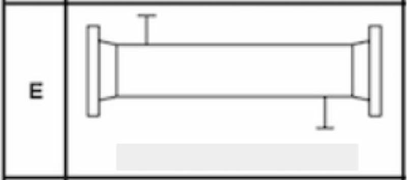
The E-type shell is by far the most common design, included in more than half of all shell and tube heat exchangers. With this style, the shellside fluid enters the exchanger at the top of one end and exits through the bottom of the other. This one-pass design suits the majority of processes with a few exceptions, Thermopedia explained.“Most shell and tube heat exchangers use a single-pass E type shell.”
TEMA F Shells
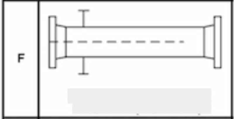
When a process requires a countercurrent stream or a major temperature cross (when the cold stream exits the exchanger at a higher temperature than the hot stream’s outlet temperature), an F type shell can be the answer.
This is a two-pass exchanger where fluid enters through one side, travels the entire length of the exchanger and doubles back around, leaving through a different outlet on the same side. The two passes are separated by a longitudinal baffle that spans the majority of the length of the shell, but ends before it reaches the far tubesheet. This allows the streams to make the double-pass.
One common concern with F-type shells is leaking around the baffle. However, there can be steps taken in the design stage to make this less likely to occur.
TEMA G and H Shells
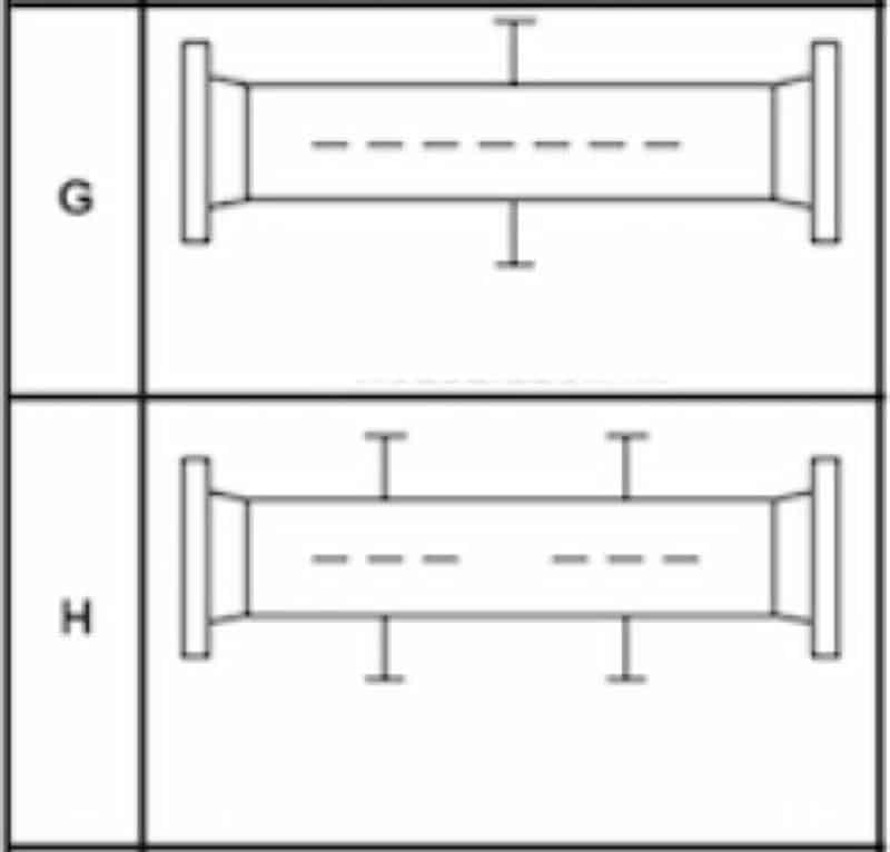
When the pressure drop needs to be kept low, as in horizontal thermosyphon reboilers, a split-shell design, or a G-type shell, is often employed. There are no baffles in a G-type exchanger and a single support plate is installed in the center of the shell.
TEMA has specific rules about how long a shell can span unsupported in a shell and tube heat exchanger. The association states that the longest a shell can be unsupported is 1.5 meters, according to CEP Magazine. With just one support plate in a G-type shell, this means that these shells can’t be longer than 3 meters. However, there are applications where a split-shell design is needed at greater lengths. In these cases, engineers can turn to the H-type shell, also called the double-split flow exchanger. Essentially, an H-type shell is two G type shells put together. This means there are two areas where the flow is divided and then reunited, as well as two support plates.
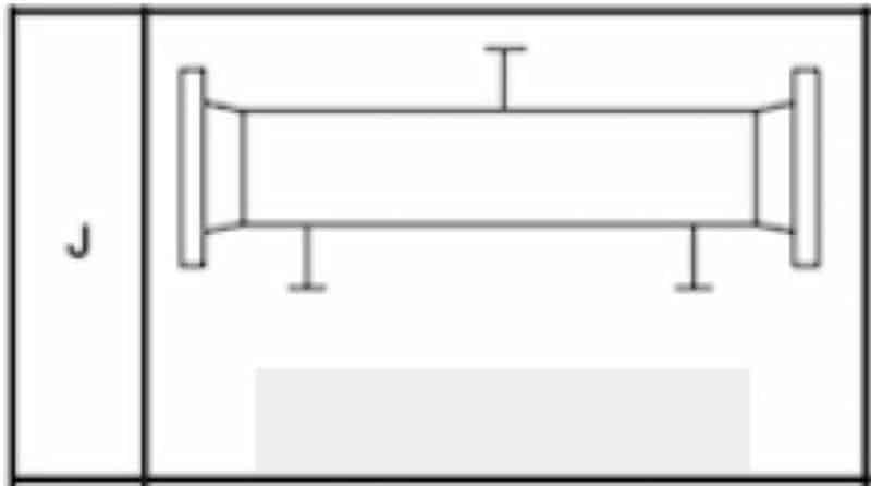
TEMA J Shells
When the pressure drop within an E type shell is too large for the exchanger to handle, there are a few remedies engineers can try. First, adding double segmental baffles could help ease the pressure drop. If this doesn’t work, engineers often turn to the J type shell, also called the divided-flow shell.
In a J type shell, the fluid enters at the center, splits into two streams (one going right and the other left) and ultimately leaves through two separate outlets. The streams are typically combined again outside the exchanger through a system of pipes. This model is also called a J 1-2 shell. In other models, the fluid can enter at two points, combine and ultimately leave in a single outlet nozzle. These may be referred to as a J 2-1 shell or an I type shell.
Large pressure drops can cause tube vibration, a problem that could cause damage to the tubes, tubesheets and shell. Because of this, J-type shells are useful for reducing the risk of damage due to vibration.
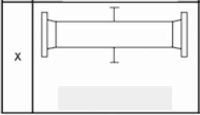
TEMA X Shells
When an application calls for a pure cross flow design or one that has very low or virtually no pressure drop, the X type is generally best. These are most often used for condensers and gas coolers.
“X-type shells are best when an application doesn’t permit any pressure drop.”
With an X-type shell, fluid enters from one side and exits directly opposite. There may be as many inlet nozzles as needed. Having multiple inlets carefully spaced along the length of the exchanger more evenly distributes the fluid across the tubes. X-type shells can also include as many support plates as needed because these run parallel to the flow and won’t interfere with the heat transfer capabilities.
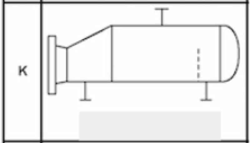
TEMA K Shells
The final type of shell that TEMA defines is the K type, which stands for “kettle.” This style is almost exclusively used for kettle reboilers, though it could also be used for chillers. Similar to X-type shells, K models are cross-flow exchangers and allow for as many support plates as needed. They are built with an enlarged shell to allow for vapor disengagement so the shellside liquid carryover is minimized. When K type shells are used in chillers, the shellside fluid is boiled while the tubeside fluid cools.
When designing the right shell and tube heat exchanger for your process, it’s important to know how different shell configurations will affect the rate of heat transfer, pressure drop, the risk of vibration and more. While the majority of processes can use the E type shell, there’s a chance that one of the other six designs suits your needs better. If you’re unsure, don’t worry: The helpful engineers at Enerquip can help determine exactly what you need.


