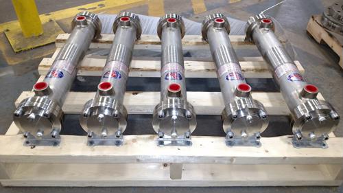
The shell is one of the most important components of a shell and tube heat exchanger, but it’s also one of the most complex elements to design, according to Chemical Engineering Progress. While the tubeside design typically deals with one flow stream, the shell has multiple instances of cross-flow and bypass streams.
Choosing the right shell for your process will help optimize the rate of heat transfer. The Tubular Exchanger Manufacturers Association determines standards for fabricating shell and tube heat exchangers, and classifies shell styles into seven different types:
TEMA E Shells
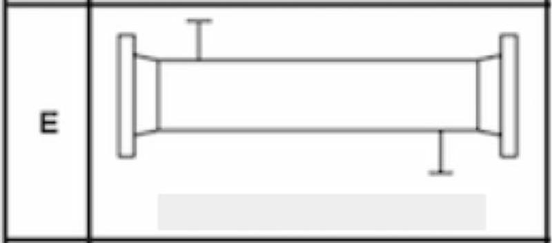
The E-type shell is by far the most common design, included in more than half of all shell and tube heat exchangers. With this style, the shellside fluid enters the exchanger at the top of one end and exits through the bottom of the other. This one-pass design suits the majority of processes with a few exceptions, Thermopedia explained.
“Most shell and tube heat exchangers use a single-pass E type shell.”
TEMA F Shells
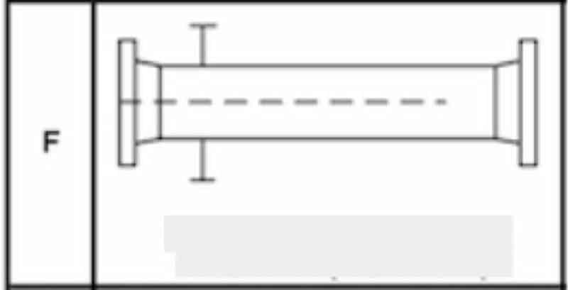
When a process requires a countercurrent stream or a major temperature cross (when the cold stream exits the exchanger at a higher temperature than the hot stream’s outlet temperature), an F type shell can be the answer.
This is a two-pass exchanger where fluid enters through one side, travels the entire length of the exchanger and doubles back around, leaving through a different outlet on the same side. The two passes are separated by a longitudinal baffle that spans the majority of the length of the shell, but ends before it reaches the far tubesheet. This allows the streams to make the double-pass.
One common concern with F-type shells is leaking around the baffle. However, there can be steps taken in the design stage to make this less likely to occur.
TEMA G and H Shells
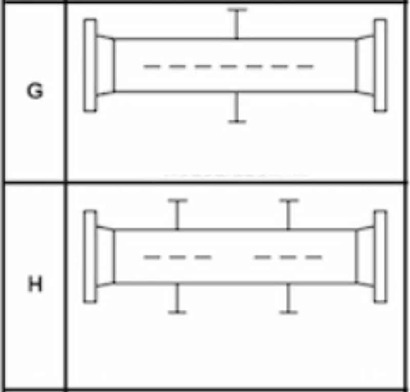
When the pressure drop needs to be kept low, as in horizontal thermosyphon reboilers, a split-shell design, or a G-type shell, is often employed. There are no baffles in a G-type exchanger and a single support plate is installed in the center of the shell.
TEMA has specific rules about how long a shell can span unsupported in a shell and tube heat exchanger. The association states that the longest a shell can be unsupported is 1.5 meters, according to CEP Magazine. With just one support plate in a G-type shell, this means that these shells can’t be longer than 3 meters. However, there are applications where a split-shell design is needed at greater lengths. In these cases, engineers can turn to the H-type shell, also called the double-split flow exchanger. Essentially, an H-type shell is two G type shells put together. This means there are two areas where the flow is divided and then reunited, as well as two support plates.
TEMA J Shells
When the pressure drop within an E type shell is too large for the exchanger to handle, there are a few remedies engineers can try. First, adding double segmental baffles could help ease the pressure drop. If this doesn’t work, engineers often turn to the J type shell, also called the divided-flow shell.
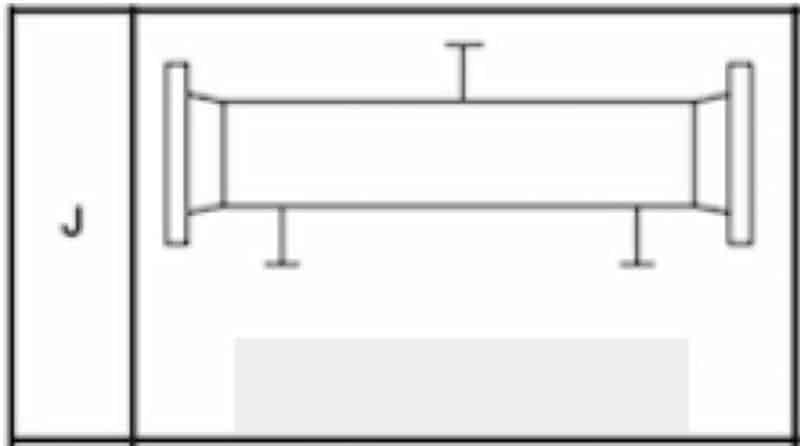
In a J type shell, the fluid enters at the center, splits into two streams (one going right and the other left) and ultimately leaves through two separate outlets. The streams are typically combined again outside the exchanger through a system of pipes. This model is also called a J 1-2 shell. In other models, the fluid can enter at two points, combine and ultimately leave in a single outlet nozzle. These may be referred to as a J 2-1 shell or an I type shell.
Large pressure drops can cause tube vibration, a problem that could cause damage to the tubes, tubesheets and shell. Because of this, J-type shells are useful for reducing the risk of damage due to vibration.
TEMA X Shells
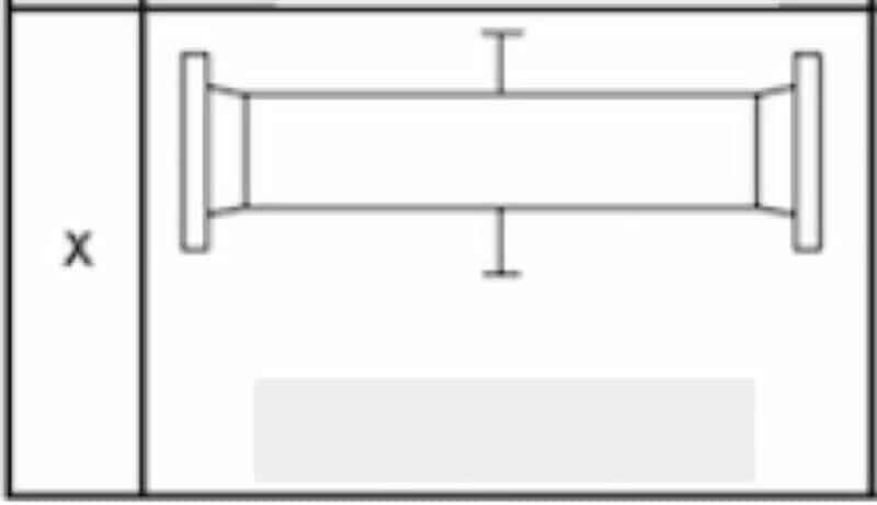
When an application calls for a pure cross flow design or one that has very low or virtually no pressure drop, the X type is generally best. These are most often used for condensers and gas coolers.
“X-type shells are best when an application doesn’t permit any pressure drop.”
With an X-type shell, fluid enters from one side and exits directly opposite. There may be as many inlet nozzles as needed. Having multiple inlets carefully spaced along the length of the exchanger more evenly distributes the fluid across the tubes. X-type shells can also include as many support plates as needed because these run parallel to the flow and won’t interfere with the heat transfer capabilities.
TEMA K Shells
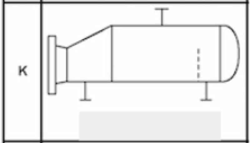
The final type of shell that TEMA defines is the K type, which stands for “kettle.” This style is almost exclusively used for kettle reboilers, though it could also be used for chillers. Similar to X-type shells, K models are cross-flow exchangers and allow for as many support plates as needed. They are built with an enlarged shell to allow for vapor disengagement so the shellside liquid carryover is minimized. When K type shells are used in chillers, the shellside fluid is boiled while the tubeside fluid cools.
When designing the right shell and tube heat exchanger for your process, it’s important to know how different shell configurations will affect the rate of heat transfer, pressure drop, the risk of vibration and more. While the majority of processes can use the E type shell, there’s a chance that one of the other six designs suits your needs better. If you’re unsure, don’t worry: The helpful engineers at Enerquip can help determine exactly what you need.

