Skip to Content
Exit

Tag Archive: Heat Exchanger Design

  1. Freezing Fouling in Shell and Tube Heat Exchangers: What you need to know

    Leave a Comment

    Fouling is a natural part of heat exchange. However, not all fouling is alike. Some types are more common but less damaging, and many can be anticipated long before installing an exchanger.

    One type of fouling that is relatively less common but potentially very damaging is freezing fouling. It’s important to understand this phenomenon, what causes it, how to prevent it and which measures to take when it does happen.

    What is freezing fouling?

    Freezing fouling, also called solidification fouling, occurs when the fluid inside the shell and tube heat exchanger seizes up and creates a block of substance that is difficult to remove. There are a number of reasons why this might happen.

    Every fluid has a freezing point, and it’s critical that those who work with heat exchangers and the fluids that go inside understand at which temperatures materials will freeze. Intuitively enough, one primary cause of freezing fouling is when the heat transfer surface falls below a fluid’s freezing point, Thermodedia explained.

    This might be the case when using a shell and tube heat exchanger to chill water. If the heat exchanger surface that is in contact with the water (i.e. the tubes if the water was entered on the tubeside) falls below 32 degrees Fahrenheit, the water will begin to freeze. How much it will freeze depends largely on the temperature difference between the tubeside and shellside fluids, among other factors. It could be a matter of a thin sheet of ice on the surface of the tubes (or shell, if the water is on that side), or a thicker mass of ice.

    Moist air can also freeze when coming into contact with a cold surface. Keep this in mind if you’ll be working with low temperatures and anticipate evaporation or mist to result from your process.

    Freezing fouling doesn’t necessarily mean the entire fluid will solidify. When using a solution, there may be various components with differing freezing points. Those ingredients that have relatively higher melting points could be challenging to keep liquid in certain processes. The solution may separate as a result, resulting not only in a partially frozen slurry, but also a liquid with different proportions of components than expected.

    Freezing fouling and crystallization fouling

    Crystallization fouling occurs when some solutes within a solution solidify and begin to accumulate on the heat transfer surface, wrote InTechOpen, an open access science, medical and technology book publisher. Depending on the solute and the conditions, people who work with shell and tube heat exchangers may refer to this phenomena with different terms, like:

    • Scaling, one of the most common, describes solid deposits that are very difficult to remove.
    • Sludge, softscale or powdery deposit describe softer, more porous, mushy or slimy deposits.

    Crystallization fouling and freezing fouling are two different events, but they do have a Venn diagram-like overlap when it comes to waxy deposits. When waxy hydrocarbons from a hotstream come in contact with the cold surface, waxy deposits can form on the heat transfer surface. These types of deposits may technically be crystallization fouling, but many people identify it as freezing fouling.

    Paraffin is one substance in particular that commonly results in a waxy precipitate, according to the Society of Petroleum Engineers’ PetroWiki. Naphthenic hydrocarbons, which like paraffin are found in crude oil, also causes wax-like deposits, but are much softer and referred to as “microcrystalline wax,” often accumulating at the the bottom of the vessel in a sludge-like substance. Since waxes have a high melting point – paraffin’s is generally between 104 and 158 degrees Fahrenheit – these deposits are often seen at ambient temperatures.

    Preventing freezing fouling in a shell and tube heat exchanger

    To avoid freezing fouling in your shell and tube heat exchanger, you must begin with understanding the fluids you’re using and how they respond to different environmental conditions, including temperature and pressure levels. Additionally, when working with solutions that contain solutes with varying freezing points, it’s critical to understand the properties of all components.

    When you know which substances you’re working with, their properties and expected behaviors, you can prevent freezing fouling by not creating the conditions in which they’ll solidify.

    With more complex substances, like crude oil, it’ll be more difficult to determine exactly which conditions will lead to the formation of solid materials. In the case of paraffin, engineers need to know the wax appearance temperature, also called the “cloud point” or “WAT.” This depends on many factors, including the weight and size of paraffin molecules, the ratio of water to oil, the composition of the oil and the presence of other substances that aid in solidification, among others.

    In some cases, freezing fouling could result from a malfunctioning component or an incorrect setting, according to an article for Plant Engineering. This may be the case if your chiller, condenser or evaporator freezes up when it’s not supposed to. In these cases, you may be unprepared for the event, and the ice formation can cause considerable damage if allowed to continue. Much like a pipe bursting during a cold winter, your tubes or shell could pop open with the pressure of the expanding ice.

    If all components are set and behaving as they should, taking precautions ahead of time could prevent a freeze-up. If you’re using antifreeze to prevent it but ice forms anyway, you may need to readjust your concentration of antifreeze. A thermal protection device or control system can also be advantageous. Finally, if you’re preparing your equipment for a seasonal shut-down in the winter, not properly and thoroughly draining your equipment can lead to freezing.

    Responding to freezing fouling

    In some cases, a certain process requires engineers to use substances that may solidify, risking the occurrence of freezing fouling. In these instances, it’s important to be prepared for if and when freezing fouling occurs so you can prevent further damage to the equipment.

    If your freezing fluid is on the shellside, you may be able to warm up the equipment using electric tracing, Chemical Processing noted. Heat exchangers exposed to cold environmental conditions can also be insulated to help prevent damage from the elements.

    However, if you know the fluid is one that would be very challenging to remove in this way, it may be better to allocate it to the tubeside. If it permanently solidifies with little or no hope of rescuing it from the exchanger, you’ll at least be able to remove the tube bundle for replacement; if an unmovable substance sets on the shellside, on the other hand, it’d be nearly impossible to take out. You may wind up needing to invest in an entirely new exchanger.

    If your freezing fouling consists of waxy deposits, you can generally remove these by melting, using steam, hot water or hot oil, or using chemicals to dissolve the wax.

    Freezing fouling may be a constant risk in your operation, or it may be an outlier event. If your equipment has sustained damage due to freezing and need a replacement part or a new custom shell and tube heat exchanger, reach out to the helpful engineers at Enerquip.

  2. How a pinch analysis can lead to energy cost savings

    Leave a Comment

    In today’s eco-conscious world, companies everywhere are taking a close look at their processes to determine just how green they are. Many find there are at least a few areas where they can improve.

    Companies may take a number of routes on their journey to greater energy efficiency. Sometimes, this includes incorporating new technology to cut costs, such as integrating a shell and tube heat exchanger to recover wasted heat. Another strategy is to re-evaluate fuel types used and adopt more renewable energy sources.

    While these are worthwhile efforts in many cases, there’s one method of increasing power efficiency and decreasing energy costs that’s often found to be the most effective, according to Oil and Gas Business. That method is ensuring your current equipment is working and being utilized to the best of its potential. A pinch analysis is a highly effective way to study the efficiency of current equipment and to design a new heat exchange system if the results show that improvement is needed.

    “A pinch analysis helps to determine the best locations for each piece of equipment.”

    Thermodynamics and the pinch point

    A pinch analysis uses the principles of thermodynamics; specifically, the first and second laws of thermodynamics, according to Mukesh Sahdev, writing for ChE Resources:

    The first law of thermodynamics

    The first law of thermodynamics states that heat is a form of energy, and energy cannot be created nor destroyed. Therefore, in all cases, including in a heat exchanger, heat cannot be created nor destroyed; only transferred.

    Sahdev writes that, in a pinch analysis, the first law relates to enthalpy changes in a heat exchanger system.

    The second law of thermodynamics

    The second law of thermodynamics is also known as the law of increased entropy. It states that even though the amount of heat (or energy) will always stay the same, the quality will change. Entropy relates to unusable energy inside a closed system.

    Sahdev explains that the second law relates to the direction of heat flow in an exchanger – it can only go from hot to cold.

    In a heat exchanger, the cold fluid will never be able to reach a temperature higher than the warmest point of the hot fluid stream. Likewise, a hot fluid stream can never be cooled to a colder temperature than the lowest point of the cold stream.

    Further, the hot stream can only be cooled to the “temperature approach,” or the minimum allowable temperature difference. This figure – the minimum allowable temperature difference – is also called the “pinch point.”

    What is a pinch analysis?

    A pinch analysis identifies the pinch point, which helps in determining the optimal size of a heat exchanger for a particular use. An analysis can also help companies recognize reasonable energy and capital cost targets. The whole idea is to determine the best locations for each piece of equipment; it’s kind of like solving a puzzle in your operation.

    There are a number of resources and technologies that companies can use to conduct a pinch analysis or to hire a professional to perform one in their facilities. Companies can also purchase pinch analysis software that will collect the necessary information. The company can then send that information to a third party to analyze it.

    Writing for Chemical Processing, Gary Faagau describes a do-it-yourself version of a pinch analysis. This is a good first step, as it avoids the time, labor and money required to conduct a formal pinch analysis.

    To begin, open a spreadsheet:

    1. In column A, list all streams in your plant that need to be heated, ordered from the lowest final target temperature to the highest.
    2. In column B, list all streams that need to be cooled, ordered from the lowest initial temperature to the highest.
    3. In column C, list all available utility heat (include steam pressures, fired heating and cost).

    Next, calculate your average heat capacity over the range of temperatures needed (as shown in columns A and B). You can use a heat exchanger simulation program to do this step.

    Then, you can begin analyzing which areas make the most sense for heat recovery. When doing this, prioritize heating or cooling capacity for your most important streams. If you don’t have a defined pinch point, you can assume an approach of 20 degrees Fahrenheit for a standard shell and tube heat exchanger, or a 10 or 15 degree approach for a more complex set of exchangers, Faagau noted.

    Benefits of a pinch analysis

    When formulating a process without a pinch analysis, engineers need to determine the design of the core process first, then the heat recovery system and finally the utility system. Each aspect of the overall design is created independently of each other.

    The pinch method, on the other hand, works with defined targets for each of the three components of the design. By taking into account the unique features of each part of the design as well as reasonable targets for each, engineers can identify opportunities for greater heat integration. Not only can this reduce energy costs, but can also contribute to a more useful heat exchanger design.

    “A pinch analysis can also contribute to a more useful heat exchanger design.”

    The pinch method was developed in the 1980s for the petrochemical industry. Its use has shown to be extremely helpful both in the planning of new facilities and the retrofitting of existing operations in various chemical engineering applications.

    Sahdev pointed out that companies have reported that pinch analyses have led to a:

    • 15 to 40 percent decrease in energy costs.
    • 5 to 15 percent reduction in capacity bottlenecks for retrofits.
    • 5 to 10 percent decrease in capital costs for new designs.

    Pinch analyses may be particularly useful for existing facilities, especially if they’ve been in operation for many years or have never been evaluated for efficiency. Considering that many petrochemical plants have been in operation since the 1960s or 1970s, as noted by Oil and Gas Business, a pinch analysis could be worth the time.

    Despite the many benefits of a pinch analysis, there are a few obstacles companies will need to overcome to make the most of them. First, they’re time-consuming and involve complex calculations. If a company decides that it would be best to conduct a formal pinch evaluation, it can be a high upfront expense. However, the savings and reduced energy expenditure may justify the cost.

    If you find that there are areas where a new or redesigned custom shell and tube heat exchanger would benefit your process, reach out to the helpful engineers at Enerquip. They’re experts at solving problems and making the best use of their exchangers.

  3. Preventing Cross Contamination in Your shell and tube heat exchangers

    Leave a Comment

    Cross contamination is a shared concern at all stages of the food industry. Chefs need to make sure their fresh veggies are kept away from their raw meat; storage facilities strive to keep common allergenic foods like nuts separate from other ingredients; and food production plants must ensure products sent through their process equipment isn’t affected by harmful bacteria, chemicals or other items.

    Shell and tube heat exchangers are popular in food production plants as a method to pasteurize fruit, vegetable or dairy products, or to achieve a desirable consistency, as in honey or maple syrup production. Cross contamination is also a risk factor in industries like pharmaceuticals and personal care.

    It’s important that these important pieces of equipment don’t contribute to any form of cross contamination. If this were to occur, it could reduce plant efficiency, lead to a ruined batch of product or necessitate a recall. There are many different ways to reduce the chances of cross contamination in your food or pharmaceutical production facility. Here are a few:

    Work with quality equipment fabricators

    The materials used in the construction of your shell and tube heat exchangers play an important role in the quality, sanitation, cleaning requirements and lifespan of your equipment. Many food industry companies turn to stainless steel for its fouling resistance.

    Choosing a stainless steel shell and tube heat exchanger is therefore a good step toward preventing cross contamination in your facility. However, you can take this one step further by finding out what sort of environment in which your shell and tube heat exchanger is fabricated.

    Cross contamination isn’t just limited to food items; you can also cross-contaminate metals. As such, it’s worthwhile to find out if your stainless steel shell and tube heat exchanger is being made in a facility that also utilizes carbon steel. If it is, there’s always a chance that this metal, which is more prone to fouling, can contaminate your equipment.

    At Enerquip, we value the integrity of stainless steel, which is why we don’t work with carbon steel. When you receive one of our heat exchangers, you can feel confident that it hasn’t been affected by this metal.

    Strategically choose your tubes

    When cross contamination does occur in a shell and tube heat exchanger, it may be caused by the shell-side fluid mixing with the tube-side fluid. To prevent this from happening, added barriers or an adjusted tube design can help.

    Enerquip’s high purity shell and tube heat exchangers are fitted with double tubesheets, which reduces the risk of cross contamination of this type. These custom and standard pharma-grade exchangers are particularly useful for pharmaceutical, nutraceutical, animal health and personal care industries.

    Double tube sheet configurations typically have a form of leak detection installed in the exchanger. If a leak were to occur in these models, the fluid should drain away from the exchanger and into a safety container rather than mixing with the other fluid, and alerts the operator that there is an issue to repair.

    Understand pressure differentials

    The engineers who create shell and tube heat exchangers must understand many complex formulas to know how the equipment will behave once it’s put to use. The pressure differential, or the difference between the pressures inside the exchanger, is an important one that relates to the likelihood of cross contamination. Typically, the pressure on the shellside would be less than inside the tubes. That way, if a leak springs, the product will flow into the heat transfer medium, rather than the medium mixing into the product and entering the tubes. This helps to keep the negative effects of a cross contamination incident as low as possible.

    Regular inspections and cleaning

    If there’s a chance of cross contamination in your equipment, it’s best to know sooner than later. Periodic visual inspections is the first step in identifying weak points and emerging problems that could lead to contamination, Business Standard pointed out. In your inspections, you might see early signs of leaks in your tubesheet or gaskets. If you catch this early, you may be able to replace or repair the damage before it leads to mixing fluids.

    You may also see early signs of fouling. If fouling is allowed to continue for too long, it can lead to spoiled product. If you do, you’ll want to clean the exchanger and determine whether you can make any changes to your process to prevent fouling. This might mean exploring new options for heat transfer fluids, cleaning more frequently or changing your sanitation methods.

    Whether you’ve experienced cross contamination at your facility or simply want to ensure you’re doing everything you can to prevent it, strategically choosing your shell and tube heat exchanger and making sure it’s kept in good condition can go a long way to help your efforts.

    To learn about Enerquip’s stainless steel shell and tube heat exchangers, reach out to our knowledgeable engineers.
  4. What you need to know about cleaning different tube configurations

    Leave a Comment

    When considering your options for a new shell and tube heat exchanger, one important factor is the tube configuration.

    Various options benefit different types of processes. For example, a floating head configuration is better suited to processes prone to significant thermal expansion because the tubes aren’t constrained by the tube sheet or the shell, and can therefore expand or vibrate without risking damage to the rest of the equipment.

    Beyond taking into account the intended use for the exchanger, and other elements like location of the exchanger or the product that will be introduced to it, it’s also a good idea to think about cleaning methods. Not all cleaning strategies are appropriate for all configurations, but all exchangers will need to be properly and thoroughly cleaned sooner or later. It’s best to know what cleaning capabilities you’ll have with a particular configuration beforehand so you can factor it into your decision, or at least prepare for new sanitation needs.

    How to Clean a Fixed Tubesheet Shell and Tube Heat Exchanger

    A fixed tubesheet is a popular shell and tube heat exchanger design for several reasons, including cost effectiveness and ease of cleaning. Since the tubes are straight and the tubesheet is welded straight to the shell, construction is relatively simple.

    To clean a fixed tubesheet shell and tube heat exchanger, the bonnet first needs to be removed. This is a relatively simple task with this configuration. The insides of the tubes can be cleaned mechanically, and the straight configuration makes it easy for brushes, hoses or other cleaning supplies to be fed into the bores. The tubes can also be cleaned chemically, and running the cleaning solution through the tubes is fairly easy, again, because of the straight design.

    While cleaning the tubeside is pretty straightforward, shellside cleaning is a bit more complicated with fixed tubesheet designs. Because the tubesheet is welded to the shell itself, it’s nearly impossible to mechanically clean the outsides of the tubes. Chemical cleaning must be done instead. However, it’s critical that operators are confident that the chemical cleaning agent can be thoroughly rinsed from the shellside before operation reconvenes. Leftover residue can damage the material of construction or contaminate the product.

    The bonnet type plays a role in how easy it is to reach the tubes. L-type and N-type bonnets, which have removable covers, grant easy access to the inside of the tubes without removing any piping. The M-type bonnet does not have this removable cover, which means the entire head needs to be taken off to access the tubes.

    The difficulty in shellside cleaning isn’t always a problem. If the shellside of this heat exchanger is only used for clean fluids rather than fouling services, there’s virtually no need for future cleaning.

    How to Clean a U-Tube Shell and Tube Heat Exchanger

    As the name suggests, the tube bundle of a U-tube exchanger is curved at the end and returns the fluid back to the same side it entered, rather than providing a point of exit on the opposite end of the exchanger. Thus, only one tubesheet is required, leaving the other end free to expand or vibrate without risking damage to the rest of the construction.

    While the U-shaped bend provides benefits in some ways, it becomes cumbersome when it comes time to clean the equipment. The curve at the end of the tube makes it challenging for mechanical cleaning, unless a flexible-end drill shaft is utilized. Chemical cleaning is possible, but certain types of fouling, make it challenging – particularly scaling that hardens to the sides of the tubes and is difficult to remove without physical force. Additionally, with scales forming at the point of the bend, it may be difficult to assess whether all fouling has been completely removed. The solution to this dilemma is to use clean fluids on the tubeside with this configuration, Thermopedia pointed out.

    An articulating brush is advantageous for cleaning U-tubes.

    While cleaning the interior of the tubes on U-tube exhchangers is a challenge, the shellside is very easy. Since there’s only one tubesheet, deconstruction is simple. Once removed, the shell and the outside of the tubes can be cleaned easily.

    How to Clean a Floating Head Shell and Tube Heat Exchanger

    The floating head tube bundle configuration is the best of both worlds. Only one end of the two tubesheets is welded to the shell, allowing the other to expand as needed according to the process it’s engaging in, similar to the U-tube configuration. Meanwhile, the straight tube design makes cleaning easier, comparable to the fixed tubesheet configuration.

    These advantages make floating head shell and tube heat exchangers a favorite among operators who are concerned both about thermal expansion as well as fouling on both sides, such as petroleum refineries or kettle reboilers, for example.

    A number of methods can be employed to sanitize floating head shell and tube heat exchangers and remove fouling. Mechanical cleaning is a practical solution, as the straight tubes make it easy for brushes, bits and sprayers to reach all areas of the bores. The floating head configuration makes it easier to remove the tube bundle than with the fixed tubesheet design, so it’s easy to reach the outsides of the tubes and the interior of the shell.

    Chemical cleaning is also a possibility, especially because it’s easy to spot inconsistencies in the cleaning job. When insufficiently cleaned areas are identified, they can be mechanically or chemically cleaned again before the equipment is put back into operation.

    The bonnet type associated with a particular exchanger’s construction plays a role in how easy this configuration can be cleaned. A P-type rear header, which is an outside packed header, gives convenient access to the tubeside but does not allow the tube bundle to be removed so the shellside can be difficult to clean.

    The S-type header also allows the tube bundle to be removed, but it is hard to take apart for bundle pulling, which can cause some complications when it’s being cleaned, inspected or repaired. The T-type header is easier to dismantle and remove than the S-type, often making it a more desirable configuration, though it also tends to be a bit pricier. The W-type header is also easy to remove and is often the least expensive of the options for a floating head heat exchanger.

    Proper Cleaning Prevents Fouling

    No matter what type of shell and tube heat exchanger you have, it’s important to know how to properly clean it to prevent fouling and ensure deposits left behind won’t cause corrosion.

    To learn about the right configuration for your operation, reach out to the helpful engineers at Enerquip

    More from the Enerquip Blog

    Preventing Cross Contamination in Your shell and tube heat exchangers

    Five Important Qualities to Look for in Pharmaceutical Process Equipment

    Pharmaceutical manufacturers must meet ASME-BPE standards

    Closed-loop process cooling can help reduce water, energy use in pharmaceutical manufacturing

    Enerquip Pharma Exchangers meet cGMP’s

  5. Why Adding a Sump to Your Heat Exchanger is a Smart Move

    Leave a Comment

    Adding a Sump to a Shell and Tube Heat Exchanger

    Looking to make your shell and tube heat exchanger more efficient and easier to maintain? Adding a sump could be the simple upgrade that makes a big impact.

    Why Add a Sump?

    If your heat exchanger is being used as a condenser, integrating a sump can save space and reduce piping by eliminating the need for a separate condensate tank. Plus, it allows for the addition of high- and low-level control ports, sight glasses, vacuum lines, and other process connections—giving you more control with less hassle.

    Keep the Gunk Out

    Another big advantage? Debris management. If your system uses river water or another source prone to sediment, a sump helps capture silt and other particles before they clog up the tube bundle. By tilting the heat exchanger toward the sump, debris naturally settles out, keeping your system running efficiently and reducing maintenance downtime.

    With optional level controls and sight glasses, you can even monitor buildup and flush it out before it becomes a problem.

    Looking for more ways to improve your heat exchanger setup? Let’s talk!

    Subscribe to our YouTube page

    More from the Enerquip Blog

    How to Pressure Test Shell & Tube Heat Exchangers

    Tube Side or Shell Side: Comparing Fluid Allocation Options for Your Shell and Tube Heat Exchanger

    3 Shell & Tube Heat Exchanger Features That Affect Shell-Side Pressure Drop

    Shell and Tube Heat Exchangers: A Guide to Industry Standards

    Selecting Tube Sizing in a Shell and Tube Heat Exchanger

  6. Davit Arm Assemblies

    Leave a Comment

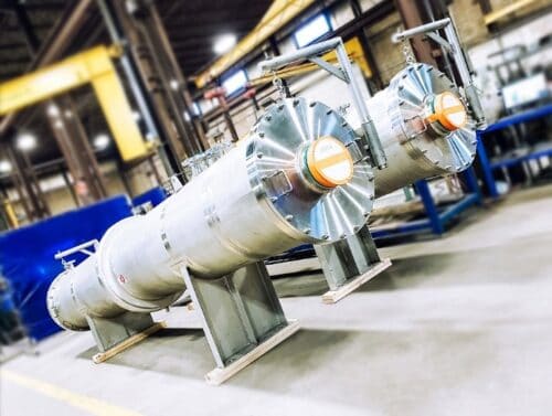
    In this video, Enerquip’s heat exchanger experts break down how davit arm assemblies can make your shell and tube heat exchangers more user-friendly, simplifying maintenance for your crew in the long run.

    Enerquip Heat Exchangers with Davit Arm Assemblies

    Subscribe to our YouTube page

  7. Advantages of Steam Bustles

    Leave a Comment

    A steam bustle, or annular distributor, is an important component of a shell and tube heat exchanger when viscosity or too much direct steam heat is a concern.

    In this video, we discuss the benefits and function of a steam bustle and how it can help improve the performance of your shell and tube heat exchanger.