Pressure drop is one of the most important design considerations before fabricating a shell and tube heat exchanger. Every heat exchanger has a maximum allowable pressure drop that depends on a number of factors, including what the unit is used for, the fluids incorporated into the process and more.
The goal of the designer is to allow the shell and tube heat exchanger get as close to the maximum allowable pressure drop without exceeding it. Surpassing this measurement can lead to an inefficient or harmful operation, where the flow rate is too high for the equipment. However, if the pressure drop is well below the maximum limit, it means the fluid could flow faster and therefore increase efficiency.
Typically, problems related to pressure drop involve having too high a flow rate, leading to excessive pressure. In these instances, designers must come up with creative strategies to limit the pressure to ensure an efficient process.
There are a number of ways to reduce the shell-side pressure drop that are related to three of the most important elements of shell and tube heat exchanger design: the shell, the tubes and the baffles.
Shell designs that limit shell-side pressure drop
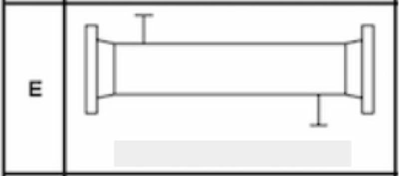
The most common shell used for heat exchanger design is the E-type, which has one inlet and one outlet valve and allows shell-side fluid to make a single pass.
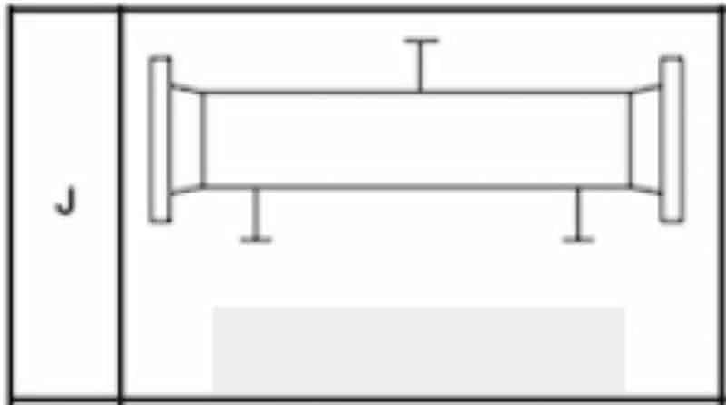
Though the E-type is most popular, it may allow the pressure drop to exceed the maximum. When this happens, designers can opt for a J-type shell, which has two outlet valves to divide the flow.
In other models, the J-type shell is reconfigured to have a single outlet but two inlet valves. This may be referred to as the I-type shell, though that’s not as common.
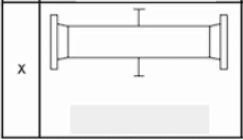
If the divided flow pattern provided by I- and J-type shells still isn’t enough to limit the pressure drop for an application, designers might turn to the X-type shell. Like the E-type, this shell has one inlet and one outlet valve. However, they are positioned directly opposite each other, rather than one being on the far right side and the other on the far left. X-type shells are most predominantly used for shell-side condensers and gas coolers, according to Thermopedia.
If the designer wishes to maintain the shell style but still adjust this section of the exchanger to modify the pressure drop, he or she might consider increasing the shell diameter. A larger diameter means shorter tubes are needed and reduces the flow area. Because of this, flow velocity is slowed down and the pressure drop is lowered.
Though this may be an effective strategy, there are a few drawbacks to this method. A larger shell diameter means the shell wall needs to be thicker and more tubes are required to get the same results, both of which contribute to higher materials cost. Additionally, shorter tube lengths mean lower tube-side velocity, which can have a negative impact on heat transfer rate.
Tube configurations that limit shell-side pressure drop
Tubes arranged in a square pattern tend to lower the shell-side pressure drop, explained John E. Edwards in “Design and Rating Shell and Tube Heat Exchangers”. A square configuration also allows for easier tube cleaning, but aside from these two benefits, there are a few drawbacks to the square pattern. Fewer tubes typically fit in a square pattern, so this design could limit heat transfer capabilities. Choosing a rotated square pattern, in which the shape resembles a diamond, can increase heat transfer rates because it allows for higher turbulence.
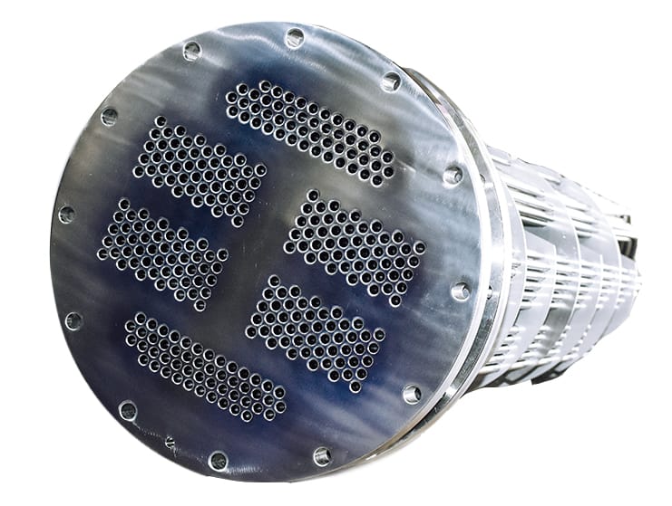
Tube pitch can also be adjusted to limit the pressure drop on the shell-side. Tube pitch refers to the distance between two adjacent tubes, according to Chemical Engineering Progress. Typically, designers may strive to have a lower tube pitch to allow for more tubes to be installed inside the shell, which maximizes heat transfer. However, increasing the tube pitch can limit the shell-side pressure drop by slowing down the flow rate. This strategy is commonly used with the X-type shell.
Baffle designs that limit shell-side pressure drop
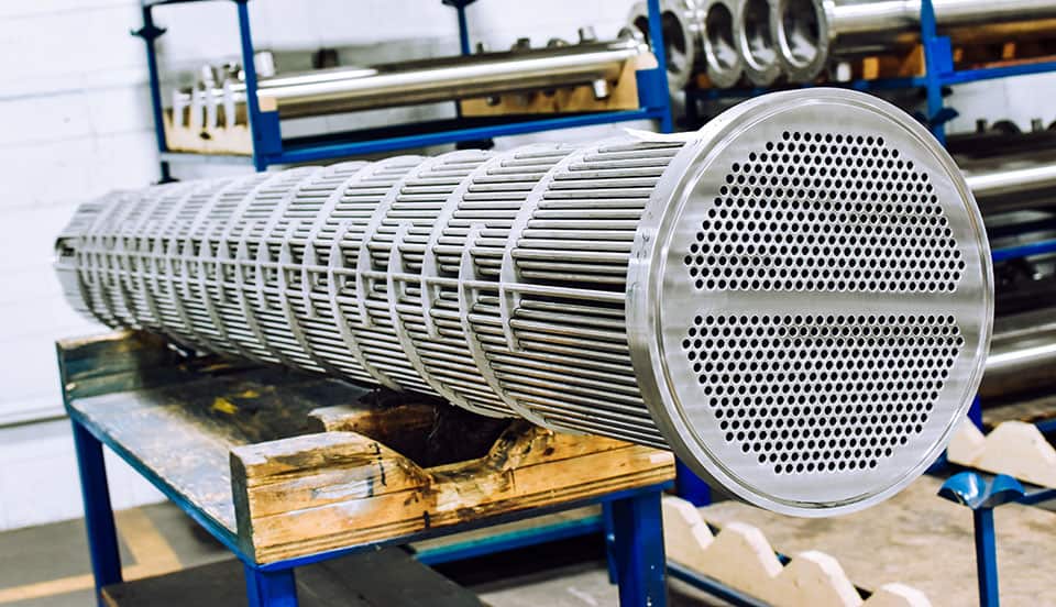
Baffles – metal plates installed throughout the shell – have multiple important purposes in shell and tube heat exchanger design, one of which is to direct the pattern and rate of flow of the shell-side fluid. The size, positioning and style of baffle can be adjusted to achieve various results, including manipulating the pressure drop.
The most common baffle design is single segmental. With this arrangement, the baffle is nearly a full circle that takes up the whole area of the shell, but with the right third sliced off for the shell-side fluid to flow around it. The next baffle is the same shape, but with the left third cut off. This pattern continues for the entire length of the shell.
Though this is the most popular style, the single segmental arrangement can allow the pressure drop to rise beyond the allowable maximum. To slow down the flow rate, designers might choose the double segmental style instead. With this design, the circular metal plate’s center third is cut instead of the right or left side. The two remaining thirds are installed across the shell from one another, and the center third is placed as the next baffle placement. This divides the shell-side flow so it goes around the central baffle, then between the side baffles.
Space between baffles creates greater cross flow
The space between baffles can also be increased to allow for greater cross flow, which can decrease the pressure drop. While this may be effective, designers still must adhere to TEMA recommendations for space between baffles. Since these plates also serve as support for the tube bundle, they can’t be placed so far apart that it allows the tubes to shake, separate or break.
Baffle cut can also make a difference in pressure drop. Baffle cut refers to the percentage of the shell diameter which is removed from the full circle plate. A larger window created by the cut reduces flow velocity, which in turn lowers the pressure drop. Again, there are limitations associated with this method, as too short a baffle may not offer adequate support to the tube bundle.
Another baffle design consideration to reduce pressure drop is the no-tubes-in-window baffle. Because the tubes and the baffles don’t interact, there’s little need to consider the supportive qualities of the baffles, which means they can be spaced farther apart as long as there are additional measures taken to support the tubes. The major downside of this design option is that much of the shell area is taken up by the baffles, not the tubes, which limits heat transfer ability.
Determining the best way to reduce pressure drop in your shell and tube heat exchanger depends on a number of factors, and there’s hardly a one-size-fits-all answer. The experienced engineers at Enerquip can help you determine the best way to design a heat exchanger that meets your operation’s needs, including pressure drop requirements.
Let’s get the conversation started. Request a quote today.

