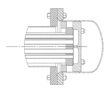
Inspecting and maintaining shell and tube heat exchangers is important to ensure that they work efficiently and safely, and to prevent costly downtime from plugged tubes or leaks. In situations where disassembly is preferred to inspect and clean all the parts of the exchanger, plant operators often opt for a floating tubesheet style heat exchanger.
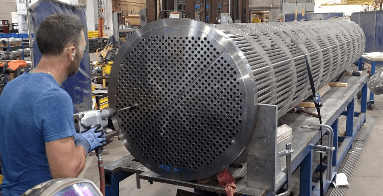
A floating tubesheet style heat exchanger consists of a removable tube bundle made up of straight tubes, tubesheets, tie rods and baffles. Depending on the weight and length of the bundle, there may also be slides or wheel assemblies to make removal of the tube bundle from the heat exchanger shell easier. The name floating tubesheet comes from the fact that the tubesheet on the tail end of the exchanger is not fixed in place, like the one on the front end of the bundle. It is allowed to “float” inside the shell, which has several advantages – and a couple of drawbacks.
Advantages of Floating Tube Sheet Exchangers
The primary advantage of this style of exchanger is full visibility of tube internals as well as the exterior of the tube bundle once it has been removed from the shell, so it can be mechanically or chemically cleaned to remove scale and fouled product. This is accomplished much more readily than a non-removable fixed tubesheet bundle or even a U-tube style bundle.
This exchanger style also makes tube repairs easier, and if a tube bundle wears out, it can be replaced with a new bundle, rather than replacing the entire exchanger. Bundles can also be upgraded to higher alloys in situations where corrosion is a concern or a cause of previous failures. If more surface area is required, replacement bundles can also be designed with a higher number of smaller tubes. This increases the heat transfer area without increasing the physical size of the exchanger.
Another advantage of this style of heat exchanger, is that the floating tube sheet allows for thermal expansion and contraction of the tubes and the shell, eliminating the need for a shellside expansion joint. In straight tube exchangers, we must account for this expansion and contraction to prevent tubes from buckling or being pulled from the tubesheets. Shell expansion joints allow for this, but also are typically the longest lead time component during fabrication and also limit options for insulating the exchanger. Eliminating the need for an expansion joint is good for shell integrity as well as the fabrication schedule.
Considerations for Floating Tube Sheet Exchangers
The primary drawback to the floating tube sheet design is complexity, which can also add cost. Because the tube bundle is removable in most styles, there are more parts involved in these types of exchangers. There are shell flanges, additional O-rings and gaskets, and retaining rings in some models that add cost and weight to the exchanger. In most cases where these are selected, our clients feel the value of the maintenance advantages outweighs the added cost.
Because the floating tubesheet and possibly the return channel must fit completely inside the shell in some styles, fewer tubes can fit into the bundle than in a fixed tubesheet model. This may require the shell to increase in diameter in order to provide the same surface area as a fixed tubesheet design.
Another drawback is a limitation on the pressure rating for the shell side of the exchanger. Because in some styles the only separation between the shell side and tubeside is an O-ring or gasket, this limits the maximum pressure it can withstand. See the chart below per the TEMA (Tubular Exchanger Manufacturer’s Association) Standard for Classes ‘B’ and ‘R’:
Four Styles to Consider
Let’s look at the four types of floating tube sheet style exchangers. TEMA utilizes a three-letter naming convention for exchanger designs, with the first letter describing the front channel/enclosure, the second letter describing the shell design, and the final letter describing the rear channel/enclosure. Among their rear channel descriptors are four different floating tube sheet designs (T, W, P & S style). Each are described below:
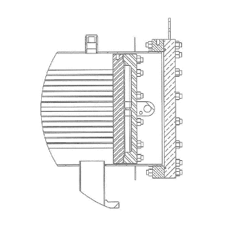
T – Style Floating Tube Sheet
The T-style exchanger is very similar to a U-tube exchanger, except instead of U-bends at the tail end of the tubes, the tubes are attached to a floating tube sheet with a return channel. The whole rear tube sheet and channel assembly fits within the shell interior.
Design features and pointers:
- Removable tube bundle, but reduced tube count since entire floating tube sheet and channel, including its bolt pattern, must fit within the shell inner diameter.
- Even number of tube passes only – like a U-tube.
- Has a removable return tube channel and shell channel to gain access to the tubes.
- No perimeter seal is needed between the bundle and the shell – similar to a U-tube.
- Must allow enough room between the shell and bolts to get a socket in for nut removal.
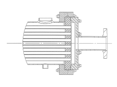
W – Style Floating Tube Sheet
The W-style exchanger has a floating tube sheet that fits entirely within the shell of the exchanger, with the shell side fluids separated from the tube side fluids by an O-ring.
Design features and pointers:
- Removable tube bundle, but reduced tube count since entire floating tube sheet must fit within the shell inner diameter.
- Only a single pass or 2-pass design can be used, since pass partitions cannot be incorporated into the return channel.
- Return channel can be machined, flanged & dished or fabricated – with or without a removable cover plate.
- Cannot be used for 3-A sanitary applications due to the tubeside crevice.
- Since shell side fluids stop at the perimeter seal around the tube sheet, this design has the greatest risk of cross-contamination between tube side and shell side fluids.
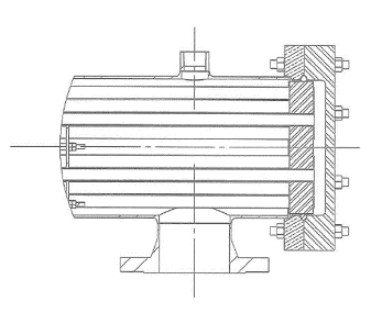
P – Style Floating Tube Sheet
The P-style exchanger is the only one of the four floating tube sheet designs that does not have a removable tube bundle. This design’s primary benefit is that it eliminates the need for an expansion joint.
Design features and pointers:
- Since the tube bundle is non-removable, there is no reduction in tube count in this style.
- There is no limitation of number of passes – odd or even.
- Return channel can be machined, flanged & dished or fabricated – with or without a removable cover plate.
- Shell side fluids stop at the lantern ring seal at the tube sheet.
S – Style Floating Tube Sheet
The S-style exchanger is the most complex and costly of the four options but is popular due to the ability to fully tear down the unit for maintenance, and the lowest risk of cross-contamination between tube side fluids and shell side utilities.
Design features and pointers:
- Removable tube bundle, but reduced tube count since entire floating tube sheet must fit within the shell inner diameter.
- Can be a single pass or multi-pass design. Caution – a single pass requires a mechanical seal on the tail end. Because of this Enerquip only builds these in even pass configurations to lower complexity and risk.
- The split lantern rings and fit-up of shell girth flanges around the floating tubesheet area add complexity.
- Includes a removable shell cover and return channel to gain access to the tubes on the tail end.
- Shell side fluids surround the return channel end, with a separate shell end cover.
- No perimeter seal is needed between the shell and the bundle – like a U-tube.
- Less restrictive on pressure ratings (due to lack of perimeter seal).
Custom Shell and Tube Heat Exchangers from Enerquip
The experts at Enerquip have experience with all four types of floating tube sheet style heat exchangers. We can assist you with determining the best option for your product and heat exchanger application to meet your heat transfer and maintenance objectives. Contact us or request a quote today.
More from the Enerquip Blog
- Decoding the Delicate Balance of Sizing Shell and Tube Heat Exchangers
- Insulation Jackets: Enhancing Efficiency and Performance of Shell and Tube Heat Exchangers
- Shell and Tube Heat Exchanger Design Options for Viscous Products
- What are Suction Heaters?
- How Annular Distributors Improve Efficiency in Shell and Tube Heat Exchangers

